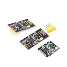
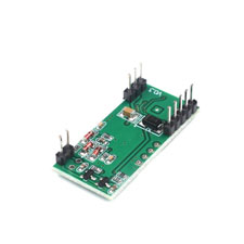
Industrial GT-24 wireless module 2.4G nRF24L01 + PA + LNA
Module
Wireless Transceiver Data Transmission Module
GT-24
Reference price
| 1: | $5.90 |
| 25: | $5.80 |
| 100: | $5.70 |
| 500: | $5.60 |
| 1000: | $5.50 |
| 5000: | $5.20 |
Product Information
Industrial GT-24 wireless module 2.4G nRF24L01 + PA + LNA
Model Number:M2021023
Gt-21 module is a 2.4GHz, 100MW, high-speed (the maximum air rate can reach 2Mbps), high stability, industrial grade wireless transceiver integrated data transmission module. The module is equipped with high-performance PCB antenna, accurate impedance matching and nrf24l01p RF chip, which has higher reliability, more power levels, longer transmission distance and lower power than nRF24L01. In addition, it also has built-in rfx2401 power amplifier chip and built-in LNA, which improves the receiving sensitivity by 10dBm and works in the ISM band of 2.4ghz-2.5ghz. The module has sufficient transmitting power, good spectrum characteristics, small harmonic, small channel crosstalk and small volume. It also has a standard spacing of 2.54mm in-line interface and 1.27mm patch interface, which is convenient for users to freely match various circuits. In addition, the gt-24 module is equipped with a built-in PCB antenna and an IPX pedestal external antenna, which greatly gives full play to the free characteristics of the module and gives users the greatest free experience.
Parameter
RF scheme: nrf24l01p, module size: 30.3 * 14.5mm (including PCB antenna), working frequency band: 2.4ghz-2.525ghz (adjustable, 1MHz step-by-step), production process: lead-free environmental protection process (machine paste), interface mode: 1 * 8 * 1.27mm / 2 * 4 * 2.54mm (patch or universal board and DuPont line direct plug), power supply voltage: 2.0-3.6vdc (not higher than 3.6V), communication level: 0.7vcc-3.3v (VCC refers to module power supply voltage), measured distance: 1000m (sunny and open, maximum power, height 2m, 250K air rate), transmission power: 4-level adjustable, maximum 20dbm (about 100MW under maximum power), air rate: 250k-2mbps (3-level adjustable 250kbps / 1Mbps / 2Mbps), turn-off current: About 30uA (test condition: CE = 0, power down mode, VDD = 3.0V), transmission current: about 90mA (the power supply capacity must be greater than 250mA), receiving current: About 20mA (CE = 1), antenna form: PCB antenna, IPEX base sub antenna, communication interface: SPI (the maximum rate can reach 10Mbps), transmitting length: 1-32 bytes (Level 3 fif0) of a single packet, receiving length: 1-32 bytes (Level 3 fif0) of a single packet, RSSI support: not supported (only simple packet loss statistics are supported) , receiving sensitivity:- 94dBm@250kbp , working temperature: – 40 – + 85 ℃, working humidity: 10% – 90%, storage temperature: – 40 – + 125 ℃
Interface
Pin 1 VCC (supply voltage, must be between 2.0-3.6v), pin 2 CE input (module control pin, see nrf24l01p datasheet for details), pin 3 CSN input (module chip selection pin, used to start an SPI communication), pin 4 SCK input (module SPI data input pin), pin 5 MoSi input (module SPI data input pin), pin 6 miso output (module SPI data output pin), pin 7 IRQ output (module interrupt signal output, low level active), pin 8 GND (ground wire, connected to the power reference ground), pin 9 GND (ground wire, which can be used for patch fixing), pin 10 GND (ground wire, which can be used for patch fixing)
Driving Mode
1. This module is nrf21l01pa-ia, and its driving mode is completely equivalent to nrf240101p. Users can operate in full accordance with nrp240101p chip manual. 2. CE pin and LNA enable pin are connected. When CE-1, LNA is turned on, and when ce-0, LNM is turned off. This operation is completely consistent with the transceiver mode of nrf241.01, that is, the user does not need to care about LNA operation. 3. CE can be connected to high level for a long time, but when some registers of the module are connected, it must first be set to the power down mode of power down. It is recommended to connect CE to port 10 of the single chip microcomputer. 4. IRQ can not be connected. SPI query can be used to obtain the interrupt status, However, it is recommended to connect with the external interrupt of the single chip microcomputer. 5. The timing operation of the CE pin of the module can adopt the high-level time mentioned in the nrf24l01p technical manual that is greater than 10us. However, our company also suggests that SPI operation should be preceded by high-level CE, and then set low CE after maintaining the high-level time of 1ms after the completion of launch interrupt. The purpose of this is to switch to the receiving mode immediately after gt-24 is sent, At this time, if ce-0, LNA has been turned off, which is not conducive to receiving sensitivity. 6. Pay attention to good grounding, large area paving and small power ripple. Increase the filter capacitor and try to be close to the VCC and GND pins of the module
Tip
1. Static electricity: the high-frequency simulator has static electricity sensitive characteristics, so please avoid human contact with the electronic components on the module as far as possible. 2. Welding: during welding, the electric soldering iron needs to be well grounded, and the production personnel need to wear the grounded wired static Bracelet during mass production. 3. Power supply: the power quality has a great impact on the performance of the module, please ensure that the power supply of the module has small ripple, Be sure to avoid frequent and large power jitter. TT type filter (ceramic capacitor / / tantalum capacitor + inductor) is recommended. 4. Ground wire: the module ground wire adopts a single point grounding mode. It is recommended to use 0 ohm resistance or 10MH inductor, which is separated from the circuit reference of other parts. 5. Antenna: the installation structure of the module antenna has a great impact on the performance of the module. Be sure to ensure that the antenna is exposed, preferably vertically upward. When the module is installed inside the shell, High quality external long wires can be used to extend the antenna to the outside of the shell. The antenna cannot be installed inside the metal shell, otherwise the transmission distance will be shortened. 6. Interference: if there are other frequency band wireless modules in the same product, it is necessary to reasonably plan the frequency and adopt shielding and other measures to reduce the impact of harmonic interference and mutual interference. 7. Crystal oscillator: if there is a crystal oscillator near the circuit board where the module is located, please increase the linear distance between the module and the crystal oscillator as much as possible
The communication distance is very close and does not reach the ideal distance at all
1. Obstacles: due to its physical characteristics, the penetration of 2.4G band is poor. When there is a straight-line communication obstacle, the communication distance attenuation is large. 2. Interference sources: temperature, humidity and co frequency interference, which will increase the communication packet loss rate (seawater absorbs radio waves, so the sea water edge test effect is poor) 3. Metal objects: there are metal objects near the antenna or placed in a metal shell, The signal attenuation will be very serious. 4. CE pin: the CE pin does not maintain a high level during transmission, which will reduce the reception sensitivity when receiving the response signal. 5. Parameter value: the power register is set incorrectly, and the air rate is set too high (the higher the air rate is, the closer the distance is) 6. Low voltage: the power supply voltage is lower than 3.3V, and the lower the voltage is, the smaller the transmission power is
Module Heating
Power supply voltage: please check the power supply to ensure that it is between 2v-3.6v. If it exceeds 3.6V, the module will be permanently damaged. Stability: please check the stability of the power supply. The voltage cannot fluctuate greatly and frequently. Anti static: please ensure anti-static operation during installation and use. High frequency devices are sensitive to static electricity. 5V level: if the communication line uses 5V level, 1k-5.1k electronics must be connected in series (not recommended, there is still a risk of damage)
